Grundig CF - 5500 calibration and head adjustment

Moderator: timundstruppi

Darkwood
Beiträge: 7
Registriert: So 5. Jan 2025, 22:37

Grundig CF - 5500 calibration and head adjustment

Beitrag von Darkwood »

Hello, I’m an old grundig fan but new on the forum :)!

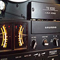
I see lot of good posts that helped me to service my grundig equipment. I have 5000 system, v5000 t5000 and cf5500 mk1.

So about 5 years ago I serviced my cf 5500, the usual stuff: changed 2200uf capacitor cleaned the potentiometers changed the idler gear and oiled the mechanism.

Recently I had to open it again because the recording on one channel was braking, it was the VAT potentiometer problem so I’ve bridged it, and everything started working again.
Over the years I’ve bought equipment for adjusting audio equipment, so I started electrical adjustments with service manual with my knowledge of German and with translator help :).

First I’ve bought good m300 adjustment jig and adjusted head height, it was ok, but I’ve noticed that the head tilt was off. When I put the tip of the jig on the head surface you could clearly see that light was coming trough and that the head was not parallel to the jig so I gently bended the head (that is the procedure in service manual described) until it was ok. I don’t know if I did it right? I was scared not to break the head or mechanism.

Then I’ve adjusted the playback level with Hanspeter Roth alignment tapes and verified with ANT calibration tapes. i’ve used 200nW 400hz tone and adjusted both channels on the test points for 580mv the led shows 0db which is correct I think.
One thing that bothers me is that the factory calibration was way off. The potentiometers were on 2 o’clock like in every grundig cf 5500 I’ve seen on the internet but now for left channel is on 11 o’clock and for right channel is on 1 o’clock.
The left channel was stronger, I don’t know if that i right or they should be in factory position with 580mv?

Then I’ve adjusted the azimuth and the tape deck is calibrating tapes normally.

So my concern is did I do everything right? Is everything electrically ok because the potentiometers for playback levels are not on 2 o’clock like in many grundig decks I’ve seen?
I hope I’ve not damaged the head by adjusting tilt?
Should I make some more adjustments?

I would also like to ask cf 5500 owners, are calibrations settings the same for side A and B or they are different a little bit and need correction for each tape side?

Thank you in advance
And best regards!
Benutzeravatar
timundstruppi
Beiträge: 2458
Registriert: Do 29. Sep 2016, 17:25
Wohnort: schloss mühlenhof

Re: Grundig CF - 5500 calibration and head adjustment

Beitrag von timundstruppi »

I don't know exactly which trimmers were used in the CF 5500, but it could of course be that they cause errors.

I've been replacing trimmers in the old Grundig Hifi components more and more recently. Now I replace all old idle current trimmers in the amplifiers.

Someone here in the forum just had a trimmers that, like my devices, sometimes completely fell apart.

I think you'll get an answer from the cassette deck professionals here shortly.
Darkwood
Beiträge: 7
Registriert: So 5. Jan 2025, 22:37

Re: Grundig CF - 5500 calibration and head adjustment

Beitrag von Darkwood »

Yes exactly!
When I replaced all capacitors in v5000 and when I started to adjust the idle current with just a little twist of the potentiometer one output transistors blew up, and they were all fine, factory stock :(. I had to buy another amp to transfer the transistors, because I wanted everything to be in factory state as much as possible.
Then I also replaced the trimmers and the idle current was easily set.
Benutzeravatar
mampfi
Administrator
Beiträge: 1733
Registriert: Mo 12. Okt 2015, 22:07
Wohnort: Eislingen

Re: Grundig CF - 5500 calibration and head adjustment

Beitrag von mampfi »

Hello, nice to hear from international CF 5500 Fan.

Do you use a Willy Herman WHS 300 gauge, or a gauge from anywhere?
I think you did it the right way to correct the tilt position from the playback head. But i never had a wrong tilt position on all the cf 5500 from now until back to the beginning.
And notice, the height from the erasehead is for 99,99% to high! To correct this, you have to remove material from the erasehead!
I think Grundig noted this issue and corrected this in the CF 5500-2 Model. Because the eraseheads in the CF 5500-2 Models are almost perfect.

Wich testpoints did you use for measuring the 580mV? I build an adapter from the internal headphone socket to cinch.
So i can use the nakamichi t100 for calibrating.
Yes if the 580mV are correct, the yellow 0dB LED has to light up.

Normally the two potentiometers on the playback board stands in the same position for 580mV on the testpoints.
So i think that is in fact something is not correct. Maybe a problem with the playback board?
Switch the channels from the playback head to see if the issue switches to the other channel or stay.

In the past i had several problems with the tda 1195. This IC is for switching the playback and record signal.
And also for Calibrating. Maybe you can measure the signal incoming and outgoing on the tda 1195?

I never checked the calibration on A and B sides from a cassette. I make the calibration one time and use it for the hole cassette.
And think about... one LED more or less is not critical for calibrating...maybe you loose 1khz in frequency response......

You're welcome for more questions. So i can dust off my english a little bit. :D
Jede Menge Grundig Zeugs, garniert mit etwas Revox, Braun, Dual und Sony, an 5 Anlagen.

Grundig forever :D
Darkwood
Beiträge: 7
Registriert: So 5. Jan 2025, 22:37

Re: Grundig CF - 5500 calibration and head adjustment

Beitrag von Darkwood »

Hello mamphi, and thank you for your reply!

I have a abex copy jig that was professionally made by some guy on tapeheads forum and he sold it via ebay. I think it’s ok.
I bought another cf 5500 in bad cosmetic condition in brown color because it had like new function keys. I swapped the keys and realized that they are not the same color :)! I didn’t knew that the color of the keys is different from silver and brown model. So I put my old keys with worn out marks, because they are silver snd shiny, and also clean them, they now work like feather touch :).

I tested the jig with brown grundig and the height and tilt are ok, the screws are untouched locktite is still on them.

On silver grundig the erase head has ok height.
I put the tip of the jig against flat part of the record/playback head and it looked like the head is tilted to the transport i slightly pushed it towards me and the tip of the jig lays flat on the head. I then corrected the tape height and adjusted the azimuth. Azimuth screw is now almost all the way screwed, don’t know if this is ok, but azimuth is properly aligned according to oscilloscope and test tape.
I checked the tape path with abex mirror tape, and the tape doesn’t curl or touch the head guides.
Also I noticed one thing, when you loosen the head height screw the head moves up and down (about 1mm) so I had to adjust so that to head surface is horizontal.

I measured the 580mv 400hz 200nWb from S3 and S5 point, that is the connection between playback board and horizontal board if I’m right.
Multimeter in AC mv range, one probe on the pin and second probe on the chassis. One channel was 693mv I forgot the value of other.. I corrected to 580mv both channels. The value jumps from 575-595mv. It’s hard to set it spot on. On right channel when I set the 580mv the first red LED on meters was flickering, I just touched the potentiometer for LED display and set it that only yellow LED shines, on left channel was ok, only yellow LED.
And now potentiometer for right channel is on 2 o’clock and for left about 12 o’clock.

Do you suggest to unsolder wires from playback head and reverse them?

I clean all potentiometers and switches with contact spray, and I had to put a lot :)!

I didn’t change capacitors only 2200uf one on power supply board.

How can determine that the IC is bad? How to measure it? Do you think that some capacitor is bad on playback board?

Thank you and sorry for long post :)
Benutzeravatar
mampfi
Administrator
Beiträge: 1733
Registriert: Mo 12. Okt 2015, 22:07
Wohnort: Eislingen

Re: Grundig CF - 5500 calibration and head adjustment

Beitrag von mampfi »

Ok, so we hope the avex copy is 100% exactly. I wrote this, because i have an original WHS 300 gauge and a copy from ebay kleinanzeigen.
This one i have to adjust to my WHS 300 one. I had to adjust screws in the back. So...i only use this alternative stuff for the cheaper ones of cassettedeck.
Yes indeed the colours from the keys silver & brown are different. Amazing what the done cosmeticaly in the early 80's.
There are a few items, who grundig used to long azimuth screws. Really..... In this case you screwed the azimuth screw all the way down, and the azimuth is still not correct aligned. So you have to shortened the Azimuth screw........unbelievable.....

The measuring point for 580mV playback level is S303 & S305 (you meant this?) or S401 & S403 from headphone socket (is the same).
You described the level adjustment correctly, so i assume that theres is no fault.

To change the playback channels i prefer to change the cables in the plug from the playback head.

With exception the power supply i had no problems with capacitors in the cf 5500.
To measure the tda1195 is sometimes a littlebit tricky. Because there are Symptoms like echoes in record mode and terrible tones in playback
with fully light on the vu meters.

Use the record and playback schematic to read the pins for level in- and outgoing.
Jede Menge Grundig Zeugs, garniert mit etwas Revox, Braun, Dual und Sony, an 5 Anlagen.

Grundig forever :D
Darkwood
Beiträge: 7
Registriert: So 5. Jan 2025, 22:37

Re: Grundig CF - 5500 calibration and head adjustment

Beitrag von Darkwood »

I’m currently restoring technics rs-m280, I will finish it today, and then I will open grundig again and check what you told me.

I don’t have any problems in the recording or calibration. The VU meters are working properly.

By the way I wanted to share the way how to repair VAT potentiometer.

I used thin coper foil and cut it to the exact shape of previous soldering contacts. Then I glued it down to potentiometer board.
Then to make the contact to the conductive trace I used silver paint (Locktite brand) that is used to repair car rear window heater. It dried about 24h hours and then you can install it and solder it :).
I did this to vat potentiometer on my brown grundig which I bought it for spare parts. :)

I will open the deck and take pictures for you to see head tilt playback board and everything.

Do you by any chance have NOS alps head for grundig? I would like to buy one to have it as a spare :)

Best regards
Benutzeravatar
timundstruppi
Beiträge: 2458
Registriert: Do 29. Sep 2016, 17:25
Wohnort: schloss mühlenhof

Re: Grundig CF - 5500 calibration and head adjustment

Beitrag von timundstruppi »

Not only the housing has a different color and the buttons, but also all the switches and buttons on the potentiometers, even the background of the VU meter has a different color.

My initial question: Are the trimmers cause problems with the CF5500? That was not answered directly. But I haven't had any problems there yet.

-------------------------
Regarding the v5000, I don't know whether it made sense to adopt a single transistor from another device.
There are a lot of discussions about having the gain factors of the end transistors as equal as possible. I got the information from a TI chip-developer: that makes a lot of sense to keep the same UBE at the transistors of the differential pair. Some manufacturers even have two transistors in a common housing in order to have thermal coupling, then the transistor pair has six pins. They want to have the minimum voltage at the DC balance.
----------------------
Darkwood
Beiträge: 7
Registriert: So 5. Jan 2025, 22:37

Re: Grundig CF - 5500 calibration and head adjustment

Beitrag von Darkwood »

Hello, I will check the trimmer potentiometers and clean them.
Maybe they are dirty so that’s the reason for different position among them.

I didn’t use only one transistor from the V5000 I changed them all. Also the driver transistors. Because the donor v5000 was in factory state except the poor outside look..

I also had a problem with the power switch, I had to change it because some “oil” from connector cable damaged the switch. No matter how I try to clean it, It always was turned on.
Benutzeravatar
timundstruppi
Beiträge: 2458
Registriert: Do 29. Sep 2016, 17:25
Wohnort: schloss mühlenhof

Re: Grundig CF - 5500 calibration and head adjustment

Beitrag von timundstruppi »

If you desoldered the switch, you can open it.
Clean it with the correct contact oil and normal paper for writing. Wacker chemistry Tuner 600, WL and Kontakt 61, Not Kontakt 60
Contacts are nearly black before cleaning.
I take a little bit of vaseline to the inner contacts of the switch.

If the plastic is broken and the lever of the switch is shaky you can fix it. I made a thread about this.

So enough of V5k.
Back to the CF5k5...
Antworten

Zurück zu „CF 5500 / Strich Zwo“